SoC Integration Testing: Hw/Sw Test Coordination (Part 1)
28 Mar 2021
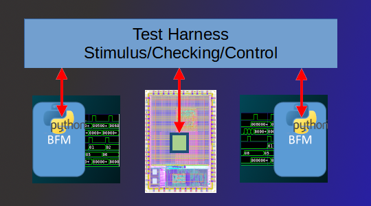
IP- and subsystem-level testbenches are quite monolithic. There is a single entity (the testbench) that applies stimulus to the design, collects metrics, and checks results. In contrast, an SoC-level testbench is composed of at least two islands: the software running on the design’s processor and the external testbench connected to the design interfaces. Efficiently developing SoC tests involving both islands requires the ability to easily and efficiently coordinate their activity.
There are a two times when it’s imperative that the behavior of the test island(s) inside the design and the test island outside the design are coordinated – specifically, the beginning and end of the test when all islands must be in agreement. But, there are many other points in time where it is advantageous to be able communicate between the test islands.
Especially when running in simulation, the ability to efficiently pass debug information from software out to the test harness dramatically speeds debug.
It’s often useful to collect metrics on what’s happening in the software environment during test – think of this as functional coverage for software.
Verifying our design requires applying external stimulus to prove that the design (including firmware) reacts appropriately. This requires the ability to coordinate between initiating traffic on external interfaces and running firmware on the design processors to react – another excellent application of hardware/software coordination.
Often, checking results consumes a particularly-large portion of the software-test’s time. The ability to offload this to the test harness (which runs on the host server) can shorten our simulation times significantly.
Key Care-Abouts
When it comes to our key requirements for communication, one of the biggest is efficiency – at least while we’re in simulation. The key metric being how many clock cycles it takes to transfer data from software to testbench. When we look at a simulation log, we want to see most activity (and simulation time) focused on actually testing our SoC, and not on sending debug messages back to the test harness. A mechanism with a low overhead will allow us to collect more debug data, check more results, and generally have more flexibility and freedom in transferring data between the two islands.
Non-Invasive
One approach to efficiency is to use custom hardware for communication. Currently, though this may change, building the communication path into the design seems to be disfavored. So, having the communication path be non-invasive is a big plus.
Portable
Designs, of course, don’t stay in simulation forever. The end goal is to run them in emulation and prototyping for performance validation, then eventually on real silicon where validation continues -- just at much higher execution speed. Ideally, our communication path will be portable across these changes in environment. The low-level transport may change – for example, we may move from a shared-memory mailbox to using an external interface – but we shouldn’t need to fundamentally change our embedded software tests or the test behavior running on the test harness.
Scalable
A key consideration – which really has nothing to do with the communication medium at all – is how scalable the solution is in general. How much work is required to add a piece of data (message, function, etc) that will be communicated? How much specialized expertise is required? The simpler the process is to incrementally enhance the data communicated, the greater the likelihood that it will be used.
Current Approaches
Of the approaches that I’ve seen in use, most involve either software-accessible memory or the use of an existing external interface as the transport mechanism between software and the external test harness. In fact, one of the earliest cases of hardware/software interaction that I used was the Arm Trickbox – a memory-mapped special-purpose hardware device that supported sending messages to the simulation transcript and terminating the test, among other actions.
In both of these cases, some amount of code will run on the processor to format messages and put them in the mailbox or send them via the interface.
Challenges
Using a memory-based communication is generally possible in a simulation-based environment – provided we can snoop writes to memory, and/or read memory contents directly from the test harness. That doesn’t mean that memory-based communication is efficient, though, and in simulation, we care a lot about efficiency due to the speed of hardware simulators.
Our first challenge comes from the fact that all data coming from the software environment needs to be copied from its original location in memory into the shared-memory mailbox. This is because the test harness only has access to portions of the address space, and generally can’t piece together data stored in caches. The result is that we have to copy all data sent from software to the test harness out to main (non-cached) memory. Accessing main memory is slow, and thus communication between software and the test harness significantly lengthens our simulations.
Our second challenge comes from the fact that the mailbox is likely to be smaller than the largest message we wish to send. This means that our libraries on both sides of the mailbox need to manage synchronizing data transmission with available space in the mailbox. This means that one of the first tasks we need to undertake when bringing up our SoC is to test the communication path between software and test harness.
A final challenge, which really ought not to be a challenge, is that we’ll often end up custom-developing the communication mechanism since there aren’t readily-available reusable libraries that we can easily deploy. More about that later.
Making use of Execution Trace
In a previous post, I wrote about using processor-execution trace for enhanced debug. I've also used processor trace as a simple way to detect test termination. For example, here is the Python test-harness code that terminates the test when one of 'test_pass' or 'test_fail' are invoked:
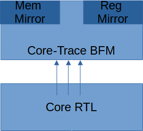
In order to support test-result checking, the processor-execution trace BFM has the ability to track both the register state and memory state as execution proceeds.
Our test harness has access to the processor core's view of register values and memory content at the point that a function is called. As it turns out, we can build on this to create a very efficient way to transferring data from software to the test harness.
In order to access the value of function parameters, we need to know the calling convention for our processor core. Here's the table describing register usage in the RISC-V calling convention:
Next Steps
SoC integration tests are distributed tests carried out by islands of test behavior running on the processor(s) and on the test harness controlling the external interfaces. Testing more-interesting scenarios requires coordinating these islands of test functionality.
In this post, we’ve looked at using execution-trace to implement a high-efficiency mechanism for communicating from embedded test software back to the test harness. While this mechanism is mostly-specific to simulation, it has the advantage of simplifying communication, debug, and metrics collection at this early phase of integration testing when, arguably, we most-need a high degree of visibility.
While we have an efficient mechanism, we don’t yet has a mechanism that makes it easy to add new APIs (scalable) nor a mechanism that is easily portable to environments that need to use a different transport mechanism.
In the next post, we’ll have a look at putting some structure and abstraction around communication that will help with both of these points.
- RISC-V Calling Conventions (ABI) – https://riscv.org/wp-content/uploads/2015/01/riscv-calling.pdf
- pybfms-core-debug-common – https://github.com/pybfms/pybfms-core-debug-common
- pybfms-riscv-debug – https://github.com/pybfms/pybfms_riscv_debug
- pyhvl-rpc -- https://github.com/fvutils/pyhvl-rpc


