
Modeling DMA Test Scenarios with PSS
25 Mar 2023
If you’ve been following the blog for any length of time, you’ve likely noticed that I like to work with examples and applications when it comes to learning and understanding technology. I certainly like the tendency of applications to take knowledge out of the theoretical realm and into the practical, helping to answer the ‘why’ and ‘how’ questions about a technology.
We’ve used a simple multi-core memory test example to illustrate the first few PSS concepts:
- Actions and Components
- Modeling multi-core tests (and automating test creation)
- Specifying declarative communication relationships between actions
We could likely continue on with this example to illustrate a few more PSS concepts, but let’s move on and use a new example. In addition to showing off a few new PSS concepts, my hope is to start talking about the PSS modeling process in the context of this example.
To that end, we’ll spend a bit more time talking about the example design itself before digging into the PSS that we’ll use to create tests for it.
Wishbone DMA Engine
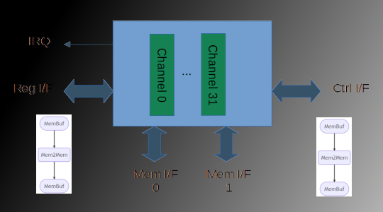
Our next example design will be the Wishbone DMA Core. While this design has been around for quite some time, and certainly isn’t the most complex, I have found that it acts as a great proxy for various hardware accelerators, autonomous communication IP, and data movers that exist in moderately-complex systems.

The DMA engine has a configurable number of channels up to 31. Any channel can perform memory-to-memory transfers using the two initiator interfaces. The DMA engine also provides a per-channel control interface that allows devices without an internal DMA engine to request data transfers.
DMA transfers are setup via the register interface. Simple transfers are configured via registers in the IP, while more-complex chained transfers are configured via an in-memory lists of descriptors.
Transfer termination can be signalled via an interrupt, and also polled by reading the channel status registers.
We’ll use this example to look at PSS features such as:
- Memory management in tests
- Modeling and managing contended resources
- Implementing test scenarios down to the register level
First Steps in PSS Modeling
Getting started is often the hardest part of any task, and creating a PSS scenario model is no different. I often advise that the best approach is to take some step, any step, since it’s easy to subsequently revise and fix the inevitable mistakes. In this way, creating a PSS scenario is very different from craft and construction projects where “measure twice cut once” remains the mantra.
There are several ways to approach the initial PSS scenario model. The best is often guided by what details stand out from the description of the device to be tested:
- The behaviors that need to be exercised via PSS scenarios
- The restrictions imposed by the device that must be obeyed by the scenario
- Interesting relationships between behaviors
- Interesting relationships between the device and others in the system
My fallback approach is to start with the individual behaviors supported by the device. The other details can always be layered on later.
Core DMA Behaviors
At the core, our DMA engine supports three operations:
- Copy memory from a source region to a destination region
- Read data from a device (eg a USB controller) and write it to a memory region
- Read data from a memory region and send it to a device
Each of these core operations has two variations based on whether the description of the transfer is stored in DMA channel registers or in an in-memory descriptor chain. But, let’s also worry about in-memory descriptors later. For now, let’s figure out what our three behaviors look like in PSS.
Component
One thing that we always need when creating a new PSS scenario model is a
component to put everything in. It’s generally a good practice to name
this component after the target of the scenario model. In our case, we
might name our component WbDma since that’s the name of the device
that we’re targeting.
component WbDma {
    // ...
}
While we could do our initial development of actions inside pss_top,
eventually we will need to move our content to a container that is
reusable. Might as well start that way instead.
Memory Copy Action
Let’s think a bit about our memory copy operation – specifically
what its pre-conditions and post-conditions are. For normal
operation, our copy action needs an initialized region of memory
from which to copy. While the DMA controller doesn’t care whether
the source region of memory is initialized, we’ll have difficulty
telling whether the operation was properly carried out unless we
can compare the result against known values.
When the DMA runs, it will copy data from the source region to a destination region of memory. We could encapsulate all of the behavior to setup test the DMA copy operation into a single action that:
- Selects and initializes a block of memory (source)
- Selects a block of memory to copy data to (destination)
- Programs the DMA to carry out the transfer
- Checks that the result is correct
But, this wouldn’t be terribly reusable. And, one great rule of thumb to use with PSS is to always think about how the actions you create today might be combined with those created by someone else for a different device and used to create a larger test scenario.
So, let’s think about our copy operation in terms of pre-conditions
and post-conditions:
pre-conditionIn order for DMA Copy to run, it needs an initialized source region of memory, a region of memory to copy to, and a DMA channel on which to run. For now, let’s focus on the memory region bit. We’ll get to the DMA channel aspect in a future post.post-conditionOnce the DMA Copy has run, a new region of initialized memory is available that other devices could use.
The source and destination memory aspect of pre-conditions and
post-conditions matches the semantics of the PSS buffer object, so we
can model this aspect by having our DMA copy operation input and
output buffer objects.
Here is what our memory-copy operation will look like as a diagram:
And, here is the code:
buffer MemBuf {
    // ...
}

component WbDMA {

    action Mem2Mem {
        input MemBuf      src_i;
        output MemBuf     dst_o;

        // ...

    }
}
We’ll figure out the contents of the MemBuf and how the DMA
transfer is implemented later. For now, though, this action
captures the pre-conditions and post-conditions that we
listed above.
Copy To/From Device
The role of a DMA engine in copying data to/from a device is a bit interesting. While the DMA engine may implement the mechanics of data transfer from the device (eg a UART) to memory, we think of the device itself as having produced the data. The DMA was just a helper to make that happen more efficiently.
We’ll come back to how, exactly, the DMA portion
of our behavior coordinates with the device portion of
our behavior, and introduce the PSS construct that enables this.
For now, let’s give ourselves place holders
for the actions that copy data to and from a device. In
PSS, as in other programming languages, creating an outline
marked with TODO: Fill in Later is a perfectly acceptable
way to make forward progress.
// ...

component WbDMA {

    action Mem2Mem {
        input MemBuf      src_i;
        output MemBuf     dst_o;

        // ...

    }

    action Mem2Dev {
        // TODO: fill in later
    }

    action Dev2Mem {
        // TODO: fill in later
    }
}
Playing with Scenarios
Even in this early state, we can start to arrange our actions to see if we’ll be able to form the test scenarios that we might be interested in.
Can we chain DMA operations together? Yes, we can.
Can we have data produced by another block be the source of the DMA copy?
Yes, so long as the buffer data types are the same.
Can we have data produced as a result of the DMA copy be the source for
another block? Again, yes, as long as the buffer data types are the same.
With very little work, we can start to build confidence that we’ll be able to create the tests that we want.
Conclusion and Next Steps
Taking the first step with a new programming language and new modeling approach can seem intimidating, but it needn’t be with PSS. With PSS, there are several ways to approach creating a scenario model based on a behavioral description of a device, and it’s easy to sketch up something quickly.
Over the next few posts, we’ll continue to refine our initial PSS scenario model for the Wishbone DMA engine and fill in the missing details by learning about new PSS constructs.
Next up: modeling memory with PSS.
Resources
- [1] Wishbone DMA Core project page
- [2] Wishbone DMA Core manual
- [3] DMA PSS Code (Viewing)
- [4] DMA PSS Code (Raw Text)