
Relating Actions with Dataflow Part2 -- Parallelism
07 May 2023
A few posts back (Relating Actions with Dataflow),
we talked about using buffer objects to form a relationship
between actions that execute sequentially. Because the actions
execute sequentially, this
relationship looks a lot like function call or the transfer of a
transaction. What is actually happening is actually a bit more
involved and much more powerful. Let’s use the DMA engine’s
‘peripheral interface’ as a vehicle to explore this declarative
data exchange aspect of the PSS language.
DMA as a Service
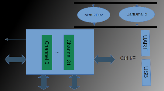
Many high-speed devices have a built-in DMA engine to offload the system processor from managing data transfers, and maximize overall system performance. For other devices, whether to use DMA comes down to the characteristics of the system. Some systems may need the extra throughput that DMA provides, while others may need the area savings that using a processor to manage data transfers brings. For this type of device, our DMA Engine’s peripheral interface provides a compromise approach: devices can be designed such they can optionally use the channel of an external DMA engine. This way, whether to use DMA or not is up to the system architect and not up to the individual IP designer.
This capability of our DMA engine means that we need to test it as a feature of the DMA IP using PSS. If we purely focus on this, our life is (relatively) straightforward. However, because we want our PSS content to be reusable, we also need to think about how the PSS test content we create for the DMA engine will interact with PSS test content created for DMA-optional devices. We will definitely want these two aspects to easily work together when testing a system where the architect has provisioned a device with an external DMA engine channel!
DMA as a Service: Theory of Operations
The DMA engine that we’re working with has a fairly simple interface when it comes to supporting external devices.
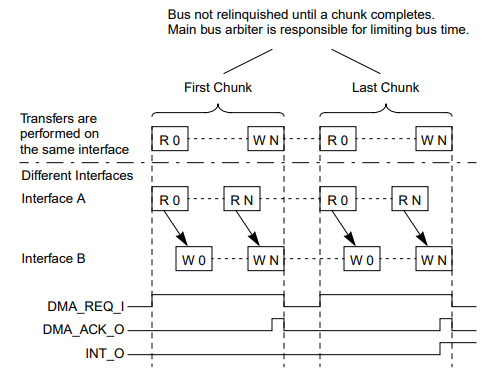
As shown in the diagram above from the DMA manual, the peripheral interface involves two signals. The peripheral device asserts the req line when it wants attention from the DMA channel. Once the channel associated with the peripheral device is prioritized, the DMA engine transfers a burst (1-N) of data to the destination address and toggles the ack signal.
Over the course of transferring a block of data, a peripheral device and the DMA engine are likely to interact many times.
Key takeaways – and PSS Rules
Now that we understand a bit more about how the DMA engine provides “DMA as a service”, it’s time to start organizing what we know into a set of ‘rules’ that we can use with PSS. As you’ve likely identified already, a fair portion of a PSS model involves ‘rules’ about data relationships (constraints), ‘rules’ about what how resources are allocated, etc.
Here’s what we know thus far:
- A peripheral device and DMA channel have a 1:1 relationship. We must ensure that the correct channel is used for a given device
- The DMA engine must be told about the external device’s address.
- The channel resource for the DMA channel to which the peripheral device is connected must be held for the duration of the transfer.
- The action representing the DMA transfer activity must run in parallel with the action representing the peripheral device activity.
Okay, so this is a bit different from operations we’ve previously
modeled with PSS. The overall data transfer operation between
memory and the device occurs at the same time as the device is
formatting that data and sending it to the world outside
our system. This certainly means that we can’t use the
buffer that we previously used to relate two actions because
the actions are not evaluated sequentially. Fortunately, PSS
provides a stream data type for specifying a data
relationship between two actions that are run in parallel.
Data to Agree On
Much like a buffer type, a stream type is a struct-like type that
holds user-defined fields. while a buffer object is used to form
a relationship between two actions that execute sequentially, a
stream object is used to form a relationship between two actions
that execute in parallel.
stream PeriphDmaStream {
    rand bit[16]        channel;
    bit[64]             periph_addr;
    addr_handle_t       mem_h;
    rand bit[16]        xfer_sz;
    rand bit[16]        xfer_cnt;
}
The definition above is for a PSS stream type that captures the
data that the peripheral device action and the DMA transfer action
must agree on. As you might note, this aligns quite nicely with the
list that we already assembled:
- The two actions must agree on the DMA channel to use
- They must agree on the address of the peripheral device, as well as where data is stored in memory.
- They must agree on how data will be transferred.
Actions to Match
Now that we’ve captured the data to be shared, let’s sketch out the actions that will actually participate in this two-part transfer. Bear in mind that our goal is that another team can implement a ‘peripheral’ action for their IP in order to make use of our DMA controller.
component WbDma {
    // ...
    action Mem2Dev {
        input PeriphDmaStream       ctrl_i;
        lock Channel                channel;

        // Acquire the requested channel
        constraint channel.instance_id == ctrl_i.channel;

        exec body {
            // Configure the DMA channel in peripheral mode
            // Program parameters
            // ...
        }
    }
    // ...
}
Now, here is the matching peripheral-device action:
component Uart {
    // ...

    // Configured during component-tree construction
    int        dma_channel;
    bit[64]    xmit_addr;

    action SendMsgDma {
        input MemBuf           dat_i;
        output PeriphDmaStream ctrl_o;

        exec post_solve {
            ctrl_o.channel     = comp.dma_channel;
            ctrl_o.periph_addr = comp.xmit_addr;
            ctrl_o.mem_h       = dat_i.addr_h;
        }

        constraint {
            ctrl_o.xfer_cnt == dat_i.size;
            ctrl_o.xfer_sz == 1;
        }
    }

    // ...
}
Remember that the DMA engine acts as an assistant in this case. Consequently, the UART action takes in the data buffer representing memory to be transmitted. The corresponding receive action would produce the buffer of memory created from the received data. In contrast, the DMA action only accepts instructions on how to setup and manage the transfer.
component Uart {
    // ...

    // Configured during component-tree construction
    int        dma_channel;
    bit[64]    xmit_addr;

    action SendMsgDma {
        input MemBuf           dat_i;
        output PeriphDmaStream ctrl_o;

        // ...
    }

    action SendMsgPio {
        input MemBuf           dat_i;

        // ...
    }

    // ...
}
In addition to making intuitive sense, this modeling approach has the big benefit of ensuring that the dataflow for UART actions is the same whether or not DMA is being used (see above).
Creating Scenarios
Let’s create a small scenario that combines the PSS model for our DMA engine with the PSS model for our UART to create a scenario where we use the DMA to automate the data transfer process.
component pss_top {
    WbDma              dma;
    Uart               uart;

    action Scenario {
        WbDma::Mem2Dev   uart_tx_dma;
        Uart::SendMsgDma uart_dma_tx;

        activity {
            // ... Create data to transmit

            // Bind control I/O together
            bind uart_tx_dma.ctrl_o uart_dma_tx.ctrl_i;
            parallel {
                uart_tx_dma;
                uart_dma_tx;
            }
        }
    }
}
In the example above, we bind the control input/output of the two actions together and traverse them in parallel. Because the two actions are connected, they will ‘agree’ on the parameters of the DMA transfer – specifically, which channel to use, what the source and destination addresses are, etc.
component pss_top {
    WbDma              dma;
    Uart               uart;

    action Scenario {
        WbDma::Mem2Dev   uart_tx_dma;
        Uart::SendMsgDma uart_dma_tx;
        WbDma::Dev2Mem   uart_rx_dma;
        Uart::RecvMsgDma uart_dma_rx;

        activity {
            // ... Create data to transmit

            bind uart_tx_dma.ctrl_o uart_dma_tx.ctrl_i;
            bind uart_rx_dma.ctrl_o uart_dma_rx.ctrl_i;
            parallel {
                parallel {uart_tx_dma; uart_dma_tx; }
                parallel {uart_rx_dma; uart_dma_rx; }
                do WbDma::Mem2Mem;
                do WbDma::Mem2Mem;
            }
        }
    }
}
Conclusion and Next Steps
Buffers and Streams – the PSS mechanism for relating sequential- and parallel-executing actions act as APIs that allow actions to interact and cooperate, despite the fact that they may have been created by multiple teams for different projects.
Using these action APIs also allows us to easily scale up our test scenarios while maintaining the validity of the test. We can build our test-specific rules on top of the rules that are built-in to the scenario because of the actions we include and their relationships. Combined with the automation provided by random generation, being able to build on top of a well-defined set of existing scenario rules significantly boosts our scenario creation productivity.
Over the past few posts, we’ve looked at some key aspects of the Accellera Portable Test and Stimulus (PSS) language:
- How PSS helps in creating bare-metal SoC tests
- Key elements of the PSS language: actions, components, flow objects, and resources
- Creating multi-core tests with PSS
- Managing memory and accessing registers with PSS
- Modeling random scenarios using rules action relationship rules
I hope this has provided a more in-depth view of the PSS language, its goals, and its capabilities. As you might guess, though, this intro to PSS has really only scratched the surface in terms of PSS language features and modeling approaches. The good news is that there are a plethora of open-source hardware designs out there that we can use to explore these topics!
References
- [1] Wishbone DMA Core project page
- [2] Wishbone DMA Core manual